Binary Number System
Electronic equipments working with two voltage levels are easy to build. Thus every digital system uses binary number system.
In the binary number system, there are only two symbols or positive values, 0 and 1. But these two values can be used to represent any quantity that can be represented using decimal or any other number system.
Logic Gates: AND, OR, NOT n XOR, NAND, NOR
A gate is simply an electronic circuit which operates on one or more signals to produce an output signal.
Gates are digital circuits because input and output signals are either on (denotes 1) or off (denotes 0). Gates are often called Logic circuits because they can be analyzed using Boolean algebra. Thus they are also called Logic Gates.
NOT Gate
A NOT Gate is a gate which takes only one input and returns the opposite signal or complement as output. If the input is 1(on or high), the output is 0(off or low).
It is also referred to as inverter buffer or digital inverter or simply inverter because it basically inverts the input signal.
Working of a NOT gate can be explained by the example:
If X is not true, then F is true.
Truth table:
|
X |
F |
|
0 |
1 |
|
1 |
0 |
Symbol:

Boolean Expression:
F = 
OR Gate
The OR Gate takes two or more signals as input and returns 1(on or high) if any one of the signals is 1(on or high). OR Gate returns 0(off or low) if all the input signals are 0(off or high). OR Gate returns only one output. The operation of an OR Gate is called Logical addition and hence the symbol used to represent OR is +.
The operation of a 2-input OR Gate can be explained by the statement:
If X or Y is true, F is true.
The working of OR Gate can be explained using the example:
Consider the following circuit. The bulb glows if any one of the switch is connected.
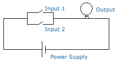
OR Gate with two input signals:
Truth Table:
|
X |
Y |
F |
|
0 |
0 |
0 |
|
0 |
1 |
1 |
|
1 |
0 |
1 |
|
1 |
1 |
1 |
Symbol:

Boolean Expression:
F = X + Y
OR Gate with three input signals:
Truth Table:
|
X |
Y |
Z |
F |
|
0 |
0 |
0 |
0 |
|
0 |
0 |
1 |
1 |
|
0 |
1 |
0 |
1 |
|
0 |
1 |
1 |
1 |
|
1 |
0 |
0 |
1 |
|
1 |
0 |
1 |
1 |
|
1 |
1 |
0 |
1 |
|
1 |
1 |
1 |
1 |
Symbol:
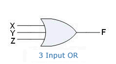
Boolean Expression:
F = X + Y + Z
AND Gate
The AND Gate takes two or more signals as input and returns 1(on or high) if all the signals are 1(on or high). AND Gate returns 0(off or low) if any one of the signals is 0(off or low). AND Gate returns only one output. The operation of an AND Gate is called Logical Multiplication and hence the symbol used to represent AND is '.'
The operation of a 2-input AND Gate can be explained by the statement:
If X and Y are true, F is true.
The working of AND Gate can be explained using the example:
Consider the following circuit. The bulb glows only if both the switches are connected.

AND Gate with two input signals:
Truth Table:
|
X |
Y |
F |
|
0 |
0 |
0 |
|
0 |
1 |
0 |
|
1 |
0 |
0 |
|
1 |
1 |
1 |
Symbol:

Boolean Expression:
F = X.Y
AND Gate with three input signals:
Truth Table:
|
X |
Y |
Z |
F |
|
0 |
0 |
0 |
0 |
|
0 |
0 |
1 |
0 |
|
0 |
1 |
0 |
0 |
|
0 |
1 |
1 |
0 |
|
1 |
0 |
0 |
0 |
|
1 |
0 |
1 |
0 |
|
1 |
1 |
0 |
0 |
|
1 |
1 |
1 |
1 |
Symbol:

Boolean Expression:
F = X.Y.Z
XOR Gate
A.K.A Exclusive OR Gate
The XOR Gate takes two or more inputs but produces one output signal. XOR Gate produces output signal 1(on) for only those input signal combinations which have odd number of 1's(on signals).
The  sign stands for
XOR Operation.
XOR gate with two inputs:
Truth Table:
|
No. of 1's |
X |
Y |
F |
|
Even |
0 |
0 |
0 |
|
Odd |
0 |
1 |
1 |
|
Odd |
1 |
0 |
1 |
|
Even |
1 |
1 |
0 |
Symbol:
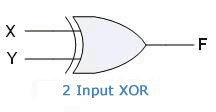
Boolean Expression:

XOR Gate with three inputs:
Truth Table:
|
No. of 1's |
X |
Y |
Z |
F |
|
Even |
0 |
0 |
0 |
0 |
|
Odd |
0 |
0 |
1 |
1 |
|
Odd |
0 |
1 |
0 |
1 |
|
Even |
0 |
1 |
1 |
0 |
|
Odd |
1 |
0 |
0 |
1 |
|
Even |
1 |
0 |
1 |
0 |
|
Even |
1 |
1 |
0 |
0 |
|
Odd |
1 |
1 |
1 |
1 |
Symbol:

Boolean Expression:

NOR Gate
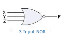
The NOR Gates takes two or more input signals and returns 1(on) only if all the inputs are 0(off). NOR Gate returns only one output.
NOR gate is basically a combination of NOT and OR gates. It can also be referred to as inverted OR Gate.

NOR Gate with two input signals:
Truth Table:
|
X |
Y |
F |
|
0 |
0 |
1 |
|
0 |
1 |
0 |
|
1 |
0 |
0 |
|
1 |
1 |
0 |
Symbol:
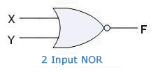
Boolean Expression:

NOR Gate with three input signals:
Truth Table:
|
X |
Y |
Z |
F |
|
0 |
0 |
0 |
1 |
|
0 |
0 |
1 |
0 |
|
0 |
1 |
0 |
0 |
|
0 |
1 |
1 |
0 |
|
1 |
0 |
0 |
0 |
|
1 |
0 |
1 |
0 |
|
1 |
1 |
0 |
0 |
|
1 |
1 |
1 |
0 |
Symbol:
Boolean Expression:

NAND Gate
The NAND Gate takes two or more input signals and returns 0(off) if all of the input signals are 1(on). NAND Gate returns one output.
NAND Gate is basically a combination of NOT and AND gates. Thus it is also known as inverted AND gate.

NAND Gate with two input signals:
Truth Table:
|
X |
Y |
F |
|
0 |
0 |
1 |
|
0 |
1 |
1 |
|
1 |
0 |
1 |
|
1 |
1 |
0 |
Symbol:

Boolean Expression:

NAND Gate with three input signals:
Truth Table:
|
X |
Y |
Z |
F |
|
0 |
0 |
0 |
1 |
|
0 |
0 |
1 |
1 |
|
0 |
1 |
0 |
1 |
|
0 |
1 |
1 |
1 |
|
1 |
0 |
0 |
1 |
|
1 |
0 |
1 |
1 |
|
1 |
1 |
0 |
1 |
|
1 |
1 |
1 |
0 |
Symbol:

Boolean Expression:

XNOR Gate
A.K.A.: Exclusive NOR Gate
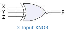
The XNOR Gate takes two or more input signals and returns 1(on) when the input combination has even number of 1's. XNOR Gate gives one output signal.
XNOR Gate is equivalent to an inverted XOR Gate, i.e. XOR Gate followed by a NOT Gate. It is also called inverted XOR Gate.

XNOR gate with two input signals:
Truth Table:
|
No. of 1's |
X |
Y |
F |
|
Even |
0 |
0 |
1 |
|
Odd |
0 |
1 |
0 |
|
Odd |
1 |
0 |
0 |
|
Even |
1 |
1 |
1 |
Symbol:

Boolean Expression:

XNOR gate with three input signals:
Truth Table:
|
No. of 1's |
X |
Y |
Z |
F |
|
Even |
0 |
0 |
0 |
1 |
|
Odd |
0 |
0 |
1 |
0 |
|
Odd |
0 |
1 |
0 |
0 |
|
Even |
0 |
1 |
1 |
1 |
|
Odd |
1 |
0 |
0 |
0 |
|
Even |
1 |
0 |
1 |
1 |
|
Even |
1 |
1 |
0 |
1 |
|
Odd |
1 |
1 |
1 |
0 |
Symbol:
Boolean Expression:

The bubble (small circle) on the outputs of NAND, NOR and XNOR gates represent complement.
Universal Gates
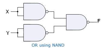
NAND and NOR Gates are called Universal Gates. This is because all the basic gates, i.e. AND, OR, and NOT gates can be created by combining these gates.
Using NAND Gate:
NOT Gate:

AND Gate:

OR Gate:
Using NOR Gate:
NOT Gate:

AND Gate:

OR Gate:

