Simple UPS |
UPS as the name suggests means Uninterrupted Power Supply. The function of a UPS is to keep the supply voltage as it is even during power cuts.
Let me explain how it works. In side a UPS ( which we use for personal computer) there is a storage cell or battery, an electronic switch, an inverter and a battery charger. Normally, when we start a UPS the main supply is present. The out put line is directly connected to the main supply and the battery is charged if necessary. During power failure, the main supply suddenly goes to zero then the electronic switch which is mainly a power transistor, changes over to the inverter. The inverter turns on immediately and the stored charge in the battery is inverted to get the required A.C. supply. This voltage obtained by the inverter is fed to the load.
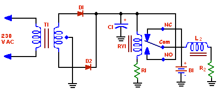
Circuit Diagram:-

Component Required:-
|
Parts List for Simple UPS |
|
B1- 6V lantern battery |
|
C1- 100µF, 16 V DC electrolytic capacitor |
|
D1, D2- Silicon rectifier rated 25 PIV at 1 A or higher |
|
Ry1- Relay, 6V DC approximately 20mA (Potter & Brumfield RS5D or equiv) |
|
T1- 12.6V center-tapped filament transformer rated 1A or higher. |
|
R1- 250kΩ, potentiometer for testing then replace with appropiate value. |
|
R2- The output load |
|
L2- Inductor. 22 Gauge, 10 -25 turns on a 1cm. Dia Soft Iron core. |
Circuit Operation:- In this project we are constructing a simple UPS an the basis of the idea behind a real UPS. This simple UPS does not contain any charger and inverter. So, DC voltage is obtained and there is no rechargeable battery.
The simple UPS contain a step down transformer, a rectifier and a filter to get a stable 6V DC supply from 230V AC mains. Then instead of a electronic switch we use a mechanical switch, a relay. The normally closed (NC) terminal is connected to the 6V battery and the normally open (NO) terminal is connected to the out of the 6V DC regulated power supply. The out put load is taken from the common terminal. We add an inductor at the out put to maintain the current during cut-off.
When the UPS is turned on the main 230 V power is present. So the AC supply is step downed then rectified then filtered to get a ripple free 6V DC supply. This voltage is fed to energies the relay coil. The relay switch comm is now connected to the normally open terminal and the load is directly connected to the DC source. When power goes off the relay coil is de-energized and the comm terminal is switched over to the normally closed terminal. That means now the current is taken from the battery. In the mean time if main power is restored, the relay coil again be energized and the comm terminal will be connected to the rectified DC terminal and the battery will be disconnected. As we all know inductance prevents the current to change rapidly in a circuit, we add an inductance in series with load. We may add a small value capacitor across the NC and Comm and NO and comm terminal of relay to prevent sparks.
Testing:- A high value resistance should be connected in series with the relay coil. So, that the standby current would be as minimum as possible. The resistance will be chosen such that it must pass the least current required for the relay to energized its input coil. We may use a pot of 100kΩ. The inductor is obtained by a thick copper wire wound on a soft iron core. The more the value of inductor the more the stable will be the current in the load during disturbance.
Application:- We can use the simple UPS with any electronic devices operated in DC power supply like radio walkman, audio systems or lights. You can construct the circuit for 3-18V DC if you get proper step down transformer and battery.
