Mike Beeper |
Mike Beeper is a mini project idea for those who want a simple Beeper circuit
instead of a beep circuit made by a 555 timer in astable mode.
Circuit Operation:-
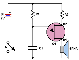
The circuit is very simple. It has an RC combination and an UJT (Unijunction
Transistor). The speaker is at the output of the UJT. When the circuit is turned
on the capacitor C1 starts charging via R1. After a certain level of charging of
C1 the input of the UJT i.e. Gate is high enough to turn on the UJT and then as
the resistance of the UJT gets low. The capacitor discharges rapidly via the UJT
channel. Again when it is fully discharged, the UJT gets in to cutoff mode
because the Gate voltage is nearly zero. Then the capacitor again charges via
R1. The process repeated and oscillation goes on. One triangular wave in audio
frequency range is generating at the output causing the Beep tone.
Circuit Diagram:-

Component Required:-
|
Parts List for MIKE BEEPER |
|
B1 - Type 216 9.v
battery C1 - 0.1. uF, 10. VDC capacitor Q1 - unijunction transistor - HEP-310 R1 - 10,000 - ohm, 1/2- watt resistor R2 - 47 - ohm, 1/2- watt resistor S1 - Spst switch Spkr - 3.2 or 8-ohm miniature speaker |
Testing:-
You can always feel an audio generator
into a mike input to check an AF system, but how do you check the mike? Saying
"woof, woof, hallo, test" gets mighty tiring. Instead, clamp the Mike Beeper to
the front of the mike with a rubber band and you’ll send continuous tone through
the mike. It lets you take your time checking the mike, connecting cable, jacks,
amplifiers, etc.
The beeper can be built in a small plastic case - nothing is critical. The
speaker may be any size from one to three inches.
Application:- Use the circuit to generate beep tones. User in other complex circuit.
