Light Activated Switch |
In this project we are going to build a light activated switch. A switch that
automatically turns on a light when it is dark and turns off automatically when
light is there. So, no more forgetting to turn off the light. The light will
automatically turned off in the morning. It is not a magic, with only a handful
of low-cost components this photo relay turns a light on or off according
general room illumination.
Circuit Operation:-
Q1 can be any general purpose pnp transistor of the 2N109 or 2N217 variety,
through greater sensitivity is obtained with the 2N2613 type. Relay K1 is a
high-sensitivity type.
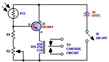
Potentiometer R2, part of a voltage divider consisting of photocell PC1, R1 and
R2, is set so that with normal illumination falling on PC1 the base bias current
(through PC1) is just below the value needed to generate the collector-emitter
current required to activate relay K1. When additional light falls on PC1,
photocell resistance decreases, thereby increasing the base bias, which causes
greater collector current to flow and the relay closes.
Circuit Diagram:-

Component Required:-
|
Parts List for Light Activated Switch |
|
B1 - 6.V battery K1 - 1000.ohm, 2.3 mA sensivity relay PC1 - RCA 4425 photocell (RCA) Q1 - SK.3004 (RCA) pnp transistor R1 - 120.ohm, 1/2. watt resistor R2 - 5000.ohm potentiometer S1 - Spst switch |
Testing:-
Probably you may not get proper value
of PC1 and Q1. Any type of pnp power transistor will work well. If you get value
of PC1 other than in the List then you have to replace the R1 potentiometer or
adjust the pot to get proper operation. Use higher rating of Relay if you use it
for TV and other electrical devices.
Application:-
This circuit can be controlled by sunlight so K1 drops out at dusk to turn on
the night light. or use a flashlight to trip K1 for "killing " TV commercials by
shorting the TV speaker connections.
