Burglar Alarm |
Did you know electronics can help you to protect your house from the thieves and unwanted person?
Take a look to my Burglar Alarm Project. This simple tool alone can guard your doors and windows with a little power consumption. This burglar alarm can be used to protect windows or glass areas by using window foil that "breaks" a circuit as the glass is broken. It is an alarm that is triggered when the protective circuit is opened.
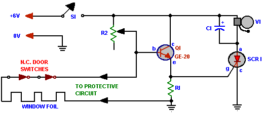
Circuit Operation:- The circuit consist of a n-p-n transistor, an alarm working on 6V DC and a SCR (Silicon Controlled Rectifier). The transistor is biased in voltage divider mode. the out put is taken from the emitter which is fed to the SCR gate. The transistor biasing circuit acts as a voltage follower to the SCR. When the protective circuit is closed, the transistor works on near cut-off stage.
It acts as a open circuit. When the protective circuit is opened or cut because of breaking of security, all the input voltage falls on the base of the transistor. Now transistor conducts. The output voltage at emitter triggers the SCR from the forward blocking state to forward conduction state and the SCR latches. The alarm is in series with the SCR. It starts ringing. There is no other way to stop the alarm even if connecting the broken window foil as the before. The commutation of SCR is possible only if there is an additional commutation circuitry. So the alarm is turned of if and only if the master switch S1 is turned off manually.
Circuit Diagram:-

Component Required:-
|
Parts List for Burglar Alarm |
| C1- 50µF, 6V DC electrolytic capacitor |
| Q1- NPN transistor, GE-20 or equiv |
| R1- 1000 Ω, ½ watt resistor |
| R2- 250kΩ, potentiometer |
| S1- SPDT switch |
| SCR1- Silicon Controlled rectifier rated 12 PIV or higher (General Electronic C106 series) |
| V1- 6V DC alarm bell |
Testing:- The recommended power supply is a AC powered regulated 6V DC source. As the transistor normally stays in cut-off, the standby current consumption is low about 100µA. To adjust, connect a voltmeter (10V DC range) across resistor resistor R1, open the protective circuit and adjust potentiometer R2 so that meter indicates a voltage rising towards ! volts. The alarm bell should ring at the time of latching of SCR and the meter will show approximate 1 Volt. If it does not, there is a wiring error. Finally, set R2 for the 1Volt mater reading, remove the meter and restore the protective circuit.
Application:- We can use the alarm in window and doors during nignt.
